6502bench SourceGen: Editors
Define Address Region
Address regions may be created, edited, resized, or removed. Which operation is performed depends on the current selection. You can specify the start and end points of a region by selecting the entire region, or by selecting just the first and last lines.
In all cases, you can specify the range's initial address
as a hexadecimal value. You can prefix it with '$', but that's not
required.
24-bit addresses may be written with a bank separator, e.g. "12/3456"
would resolve to address $123456.
If you want to set the region to be non-addressable, enter
"NA".
You can also enter a pre-label or specify that the operand should be formatted as a relative address.
To delete a region, click the "Delete Region" button.
Create
If your selection starts with a code or data line, the editor will allow to create a new address region. If a single line was selected, the default behavior will be to create a region with a floating end point. If multiple lines were selected, the default behavior will be to create a region with a fixed end point.
The address field will be initialized to the address of the first selected line.
You can create a child region that shares the same start offset as an existing region by selecting the first code or data line within that region. Note that regions with floating end points cannot have the same start offset as another region.
Edit
If you select only the address region start line, perhaps by double-clicking the operand there, you will be able to edit the current region's properties.
If the region has a floating end point, you can choose to convert it to a fixed end. The end doesn't move; it just gets fixed in place. This is a quick way to "lock down" regions once you've established their end points.
Resize
If you select multiple lines, and the first line is an address region start directive, you will be able to resize that region to the selection. By definition, the updated region will have a fixed end point.
Other notes
There is no affordance for moving the start offset of a region. You must create a new region and then delete the old one.
Regions may not "straddle" the start or end points of other regions.
Double-clicking on the pseudo-opcode of a region start or end declaration will move the selection to the other end, rather than opening the editor.
To see detailed information about an address region in the "Info" window, select the region start or end directive. You can see the current arrangement of address regions across your entire project with Navigate > View Address Map.
Override Status Flags
The state of the processor status flags are tracked for every instruction. Each individual flag is recorded as zero, one, or "indeterminate", meaning it could hold either value at the start of that instruction. You can override the value of individual flags.
The 65816 emulation bit, which is not part of the processor status register, may also be set in the editor.
The M, X, and E flags will not be editable unless your CPU configuration is set to 65816.
Edit Label
Sets or clears a label at the selected offset. The label must have the proper form, and not have the same name as another symbol, unless it's specified to be non-unique. If you edit an auto-generated label you will be required to change the name.
The label may be marked as non-unique local, unique local, global, or global and exported. The default is global. If you start typing a label with the non-unique label prefix character (usually '@', configurable in application settings), the selection will automatically switch to non-unique local.
Local labels may be "promoted" to global if the assembler requires it. Most assemblers define local scope as starting clean after each global label, but there are exceptions. If a label's name conflicts or is incompatible with the assembler, it will be renamed.
Exported labels are added to a table that may be imported by other projects (see Working With Multiple Binaries).
Edit Operand (Instruction)
Operands can be formatted explicitly, or you can let the disassembler select the format for you. By default, immediate constants and addresses with no matching symbol are formatted as hex. Symbols defined as address labels, platform/project symbols, and local variables will be identified and applied automatically.
Explicit Formats
Operands can be displayed in a variety of numeric formats, or as a symbol. The character formats are only available for operands whose value falls into the proper range. The ASCII format handles both plain and high ASCII; the correct encoding is chosen based on the operand's value.
Symbols may be used in their entirety, or, when used as constants, can be shifted and masked. The low / high / bank selector determines which byte is used as the low byte. For 16-bit operands, this acts as a shift rather than a byte select. If the symbol is wider than the operand field, e.g. you're referencing a 16-bit address in an 8-bit constant, a mask will be applied automatically.
The editor will try to prevent you from using auto-generated labels and local variables in the symbol field. These types of symbols can be freely renamed by SourceGen, and thus cannot be reliably referenced by name. You can reference a non-unique local by writing it with the non-unique label prefix character (default '@'). Ambiguous non-unique references are not allowed, so if the symbol can't be found the label will be discarded.
When you select a non-default format option, a "preview" of the formatted operand will be shown.
The MVN and MVP instructions on the 65816
are a bit peculiar, because they have two operands rather than one.
SourceGen currently only allows you to set one format, which will be
applied to both operands. If you specify a symbol, the symbol will
be used twice, adjusted if necessary. (This limitation may be addressed
in a future release.)
The BBR and BBS instructions on the W65C02
also have two operands: a direct page address, and a relative branch.
In general the direct page address is ignored, so these are treated as
branch instructions.
The bottom part of the window has some shortcuts for working with address references and local variables. These are primarily used to change the way things work when "Default" is selected. The shortcuts don't cause any changes to the recorded format of the instruction being edited. All of the actions can be performed elsewhere, by editing the label at the target address, editing the project symbol set, or editing a local variable table.
Numeric Address References
For operands that are 8-bit, 16-bit, or 24-bit addresses, you can define a symbol for the address as a label or project symbol.
If the operand is an address inside the project, you can set a label at that address. If the address falls in the middle of an instruction or multi-byte data item, its position will be adjusted to the start. Labels may be created, modified, or (by erasing the label) deleted.
The label finder does not do the optional search for "nearby" labels that the main analyzer does, so there will be times when an instruction that is shown with a symbol in the code list won't have a symbol in the editor.
If the operand is an address outside the project, e.g. a ROM address or I/O location, you can define a project symbol. If a match was found in the configured platform definition files, it will be shown; it can't be edited, but it can be overridden by a project symbol. You can create or modify a project symbol by clicking on "Create Project Symbol" or "Edit Project Symbol". You can't delete project symbols from this editor (use Project Properties instead).
It's possible to have more than one project symbol for the same address. For example, on the Apple II, reading from the memory-mapped I/O address $C000 returns the last key pressed, but writing to it changes the state of the 80-column display hardware, so it's useful to have two different names for it. If more than one project symbol has the same address, the first one found will be used, which may not be what is desired. In such situations, you should create the project symbol and then copy the symbol name into the operand. You can do this in one step by clicking the "Copy to Operand" button. (In most cases you don't want to do this, because if the project symbol is deleted or renamed, you'll have operands that refer to a nonexistent symbol. Unlike labels, project symbol renames do not refactor the rest of the project.)
Local Variable References
For zero-page address operands and (65816-only) stack-relative constant operands, a local variable can be created or modified. This requires that a local variable table has been defined at or before the instruction being edited.
If an existing entry is found, you will be able to edit the name and comment fields. If not, a new entry with a generic name and pre-filled value field will be created in the nearest table.
Edit Operand (Data)
This dialog offers a variety of choices, and can be used to apply a format to multiple lines. You must select all of the bytes you want to format. For example, to format two bytes as a 16-bit word, you must select both bytes in the editor. (If you click on the first item, then Shift+double-click on the operand field of the last item, you can do this very quickly.) The selection does not need to be contiguous: you can use Control+click to select scattered items.
If the range is discontiguous, crosses a logical boundary such as a change in address or a user-specified label, or crosses a visual boundary like a long comment, note, or visualization, the selection will be split into smaller regions. A message at the top of the dialog indicates how many bytes have been selected, and how many regions they have been divided into.
(End-of-line comments do not split a region, and will disappear if they end up inside a multi-byte data item.)
The "Simple Data" items behave the same as their equivalents in the Edit Operand dialog. However, because the width is not determined by an instruction opcode, and multiple items can be selected, you will need to specify how wide each item is and what its byte order is. For data you also have the option of setting the format to "Address", which marks the selected bytes as a numeric reference.
Consider a simple example: suppose you find a table of 16-bit addresses in the code. Click on the first byte, shift-click the last byte, then select the Edit Data menu item. The number of bytes selected should be even. Select "16-bit words, little-endian", then over to the right click on "Address". When you click OK, the selected data will be formatted as a series of 16-bit address values. If the addresses can be resolved inside the data file, each address will be assigned a label.
The "Bulk Data" items can represent large chunks of data compactly. The "fill" option is only available if all selected bytes have the same value. If a region of bytes is irrelevant, perhaps used only as padding, you can mark it as "junk". If it appears to be adding bytes to reach a power-of-two address boundary, you can designate it as an alignment directive. If you have multiple regions selected, only options that work for all regions will be shown.
The "String" items are enabled or disabled depending on whether the data you have selected is in the appropriate format. For example, "Null-terminated strings" is only enabled if the data regions are composed entirely of characters followed by $00. Zero-length strings are allowed. DCI (Dextral Character Inverted) strings have the high bit on the last byte flipped; for PETSCII this will usually look like a series of lower-case letters followed by a capital letter, but may look odd if the last character is punctuation (e.g. '!' becomes $A1, which is a rectangle character that SourceGen will only display as hex).
The character encoding can be selected, offering a choice between plain ASCII, low + high ASCII, C64 PETSCII, and C64 screen codes. When you change the encoding, your available options may change. The low + high ASCII setting will accept both, configuring the appropriate encoding based on the data values, but when identifying multiple strings it requires that each individual string be entirely one or the other.
Due to fundamental limitations of the character set, C64 screen code strings cannot be null terminated ($00 is '@').
As noted earlier, to avoid burying elements such as labels in the middle of a data item, contiguous areas may be split into smaller regions. This can sometimes have unexpected effects. For example, this can be formatted as two 16-bit words or one 32-bit word:
         .DD1    $01
         .DD1    $ef
         .DD1    $01
         .DD1    $f0
With a label in the middle, it can be formatted as two 16-bit words, but not as a 32-bit word:
         .DD1    $01
         .DD1    $ef
LABEL    .DD1    $01
         .DD1    $f0
CODE     LDA     LABEL
If this is undesirable, you can add a label at a 32-bit boundary, and reference that instead:
LABEL    .DD1    $01
         .DD1    $ef
         .DD1    $01
         .DD1    $f0
CODE     LDA     LABEL+2
With the label out of the way, the data can be formatted as desired.
Edit Comment
Enter an end-of-line (EOL) comment, or leave the text field blank to delete it. EOL comments may be placed on instruction and data lines, but not on assembler directives.
It's wise to restrict comments to the ASCII character set, because not all assemblers can accept UTF-8 input. Code generators for such assemblers will convert non-ASCII characters to '?' or something similar. If this isn't a concern, you can enter any characters you like.
There is no fixed limit on the number of characters, but you may want to limit the overall length if you're hoping to create 80-column output. Some retro assemblers may have hard line length limitations, which could result in the comment being truncated in generated sources.
A semicolon (';') is placed at the start of the comment. If an assembler has different conventions, a different delimiter character may be used. You don't need to include a delimiter explicitly in the comment field.
Comments on platform symbols are read from the platform symbol file, and cannot be edited from within SourceGen. Comments on project symbols are stored in the project file, and can be edited with the project symbol editor.
Edit Long Comment
Long comments can be arbitrarily long and span multiple lines. They will be word-wrapped at a line width of your choosing. They're always drawn with a fixed-width font, so you can create ASCII-art diagrams. Comment delimiters are added automatically at the start of each line.
For a true retro look you can "box" the comment with asterisks. You can create a full-width row of asterisks by putting a '*' on a line by itself. (Assembly source generators are allowed to use a character other than '*' for the output, e.g. they might use a full set of box outline characters, though that's somewhat against the spirit of the thing. Regardless, a solo '*' results in a line.)
The bottom window will update automatically as you type, showing what the output is expected to look like. The actual assembler source output will depend on features of the target assembler, such as comment delimiter choices and maximum line length limitations. For example, Merlin allows a leading '*' to indicate a comment, while cc65 does not, so cc65 code uses ";*' instead. Because the length limitation affects the length of the line, not just the comment text, an asterisk-boxed comment will have one fewer character per line in cc65 output.
Clear the text field to delete the comment.
You can use Ctrl+Enter as a keyboard shortcut for "OK".
The long comment at the very top of the project is special, as it's not associated with a file offset. If you delete it, you can get it back by using Edit > Edit Header Comment.
Edit Data Bank (65816 only)
Sets the Data Bank Register (DBR) value for 65816 code. This is used when matching 16-bit address operands with labels. The new value is in effect from the line where it's declared to the end of the file, even across bank boundaries. If you leave the text field blank, the directive will be removed.
A hexadecimal value from $00 to $ff can be entered directly. As with other address inputs, a leading '$' is not required. Entering "K" will set the DBR to the current address, and will automatically update if you change the address to a different bank.
The pop-up menu has a list of all banks that hold code or data. To make them easier to identify, each is shown with the label on the first address in the bank, if any.
While you can override automatically-generated data bank change directives, you can't remove them individually. You can disable automatic generation by un-checking "smart PLB handling" in the project properties.
Because the directive is frequently associated with PLB
instructions, double-clicking on a PLB opcode in the
code list will open the editor.
Edit Note
Notes are similar to long comments, in that they can be arbitrarily long and span multiple lines. However, because they're never included in generated output, options like line width formatting and boxing aren't relevant.
Instead, you can select a highlight color for the note to make it stand out. You may want to assign certain colors to specific things, e.g. blue for "I don't know what this is" or green for "this is a bookmark for the really interesting stuff". The color will be applied to the note in the code list and in the "Notes" window.
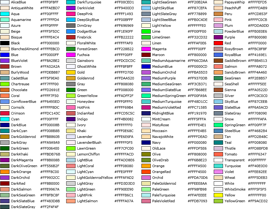
If you don't like the standard colors you can define your own.
You can do this with web RGB syntax, which uses a '#' followed by
two hex digits per channel. For example, bright red is
#ff0000, while teal is #008080. You can
also simply type a color name like "violet" so long as it appears in the
list of Microsoft .NET colors.
Clear the text field to delete the note.
You can use Ctrl+Enter as a keyboard shortcut for "OK".
Edit Project Symbol
This is used to edit the properties of a project symbol.
Symbols marked as "address" will be applied automatically when an operand references an address outside the scope of the data file. They will not be applied to addresses inside the data file. Symbols marked as "constant" are not applied automatically, and must be explicitly specified as an operand.
The label must meet the criteria for symbols (see All About Symbols), and must not have the same name as another project symbol. It can overlap with platform symbols and user labels.
The value may be entered in decimal, hexadecimal, or binary. The numeric base you choose will be remembered, so that the value will be displayed the same way when used in a .EQ directive.
You can optionally provide a width for address symbols. For example, if the address is of a two-byte pointer or a 64-byte buffer, you would set the width field to cause all references to any location in that range to be set to the symbol. Widths may be entered in hex or decimal. If the field is left blank, a width of 1 is assumed. Overlapping symbols are allowed. The width is ignored for constants.
If you enter a comment, it will be placed at the end of the line of the .EQ directive.
For address symbols that represent a memory-mapped I/O location, it can be useful to have different symbols for reads and writes. Use the Read/Write checkboxes to specify the desired behavior.
Create/Edit Local Variable Table
Local variables are arranged in tables, which are created at a specific file offset. They must be associated with a line of code, and are usually placed at the start of a subroutine. The "Create Local Variable Table" action creates a new table, and opens the editor. The "Edit Prior Local Variable Table" searches for the closest table that appears at or before the selected line, and edits that.
The editor allows you to create, edit, and delete entries, as well as move and delete entire tables (though these last two options are not available when creating a new table). Empty tables are allowed. These can be useful if the "clear previous" flag is set. If you want to delete the table, click the "Delete Table" button.
Use the buttons to add, edit, or remove individual variables. Each variable has a name, a value, a width, and an optional comment. The standard naming rules for symbols apply. Variables are only used for zero-page and stack-relative operands, so all values must fall in the range 0-255. The width may extend one byte past the end (to address $0100) to allow 16-bit accesses to $ff (particularly useful on 65816).
You can move a table to any offset that is the start of an instruction and doesn't already have a local variable table present. Click the "Move Table" button and enter the new offset in hex. You can also click on the up/down buttons to move to the next valid offset.