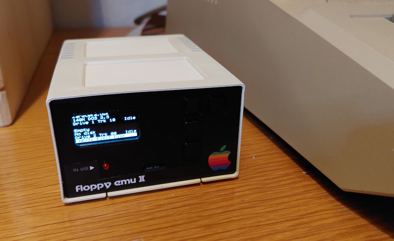
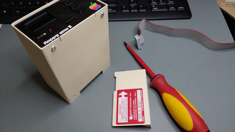
FloppyEmu Disk II Enclosure
This project contains OpenSCAD files, STL files, stickers and KiCad PCB to create a 3D-printed custom enclosure for the Big Mess of Wires - FloppyEmu - an SD-card based disk drive emulator for the Apple II computer. The custom enclosure is a look-alike of the historic "Disk II" drive, Apple's first and hugely successful original disk drive for the Apple II, introduced in 1978.
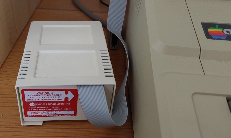
As a bonus, this project also contains a housing for the Floppy Emu DB-19 plug adapter - a separate little 3D-print to protect the adapter (see "Bonus" section below).
Credits
The idea for this 3D-printing project was triggered by similar ideas to create Disk II-shaped custom enclosures for the FloppyEmu in the AppleFritter forum - a forum for vintage Apple computer fans. See this discussion thread for more.
License
This project is released under the "Creative Commons Attribution 4.0 International Public License". See LICENSE.
The Apple logo is a registered trademark of Apple Computer Inc. Any images and photos which may show the Disk II-FloppyEmu enclosure with an Apple logo were only given as an example of how you could decorate your Disk II-FloppyEmu drive enclosure for your personal use, to match the retro look of your wonderful original Apple II computer. The 3D-printed Disk II FloppyEmu enclosure is not endorsed by Apple. This project does not grant you any rights or licenses to distribute any 3D-printed enclosures with an Apple logo.
Design
The 3D design is done with OpenSCAD. All files are available in the scad folder.
The OpenSCAD file provides an option to generate the enclosure in different sizes. The minimum scale to fit the FloppyEmu PCB is 0.6 (= 60% of the original Disk II enclosure size). Currently, this reduced size is the only variant which is tested. The photos of the enclosure also show this reduced variant. Larger sizes will still require some tweaking in the SCAD files. The full-sized variant will be supported in the future (wait for it...). You can also choose whether to use one LED (status LED only), or two LEDs (status + power LED). One LED is the default.
You can also find a ready-to-use STL files in the stl folder. These STL files apply to the tested variant (60% of the original, one LED).


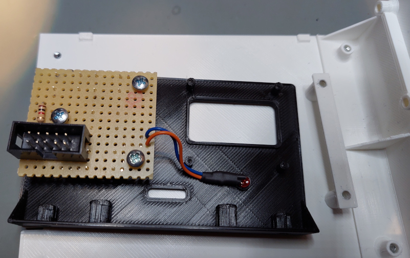
Button Panel
You will need a button panel, so you can control FloppyEmu from the front. You can build the panel manually using a perfboard or order a printed circuit board (from JLCPCB etc).
The pcb folder contains all Gerber files required for a PCB order:


Alternatively, use a perfboard to solder the push buttons manually. It's only 4 buttons and a connector (and maybe the resistor for the status LED):


Schematics and the KiCad project for the PCB are also stored in pcb folder:


The button PCB is eventually screwed to the front panel (Note: the photo does not show the latest design. The PCB is now mounted with 4 screws, one in each corner - see newer PCB design above).
Bill Of Materials
Here's what you need.
For the button panel:
- Manufactured PCB (i.e. upload the Gerber-Files to a PCB manufacturer, like JLCPCB). Alternatively use a perfboard.
- 4x "micro switch push button 6x6x7mm" (ebay etc)
- 1x 3mm LED (red)
- 1x resistor (value depends on the type and intensity of your LED, usually 330 Ohm to 1KOhm)
- "2x5 box header" or, alternatively, "2x5 straight pin header"
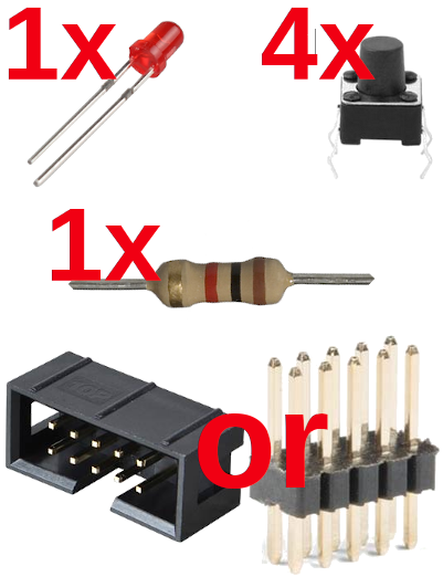
The four push buttons are very common and easy to obtain. They are similar as the onboard buttons of FloppyEmu. Except the PCB design is made for a through-hole type push buttons (not SMD buttons as on FloppyEmu). Switches with a 7mm peg are required to properly mount the printed button caps. Check on ebay searching for "micro switch push button 6x6x7mm". Your favourite electronics supplier should also have them (Germany: reichelt.de, TASTER 9303, Kurzhubtaster 6x6mm, 7,0mm).
For the button panel and LCD connector:
-
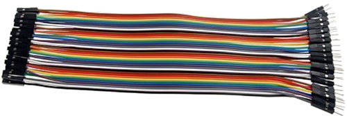
You can use simple breadboard wires ("jumper wires") to connect FloppyEmu to the button panel and LCD. They are cheap and also come with a ribbon cable. The LCD and the button panel both require 7 wires each (since 3 pins of the button panel's pin header are unused).
-
Alternatively, use "header plugs" with matching ribbon cable (2x5 for the button panel, 2x8 for the LCD) - as shown in the build photos. This is a slightly more expensive and complex solution.
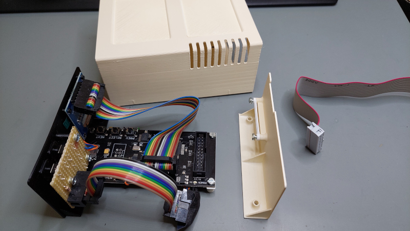
Wiring FloppyEmu
The FloppyEmu PCB does not provide convenient pins or solder pads to tap the button and LED status signals. However, it's still relatively easy to tap the required signals - as shown by these photos. The photos apply to the Revision C model of the BMOW FloppyEmu. For other revisions, better verify the wiring with a multimeter.
A single wire is enough for each push button is enough: all four push buttons, including the reset button, connect to common ground. The status LED, however, does not connect to ground: it's wired between the status output signal and +5V (via an appropriate resistor for the LED, of course). The only feasible place is to solder directly next to the LED. The status signal is on the right of the LED – as shown. Be careful when soldering – just touch the LED very briefly with the iron – otherwise the onboard LED will die.
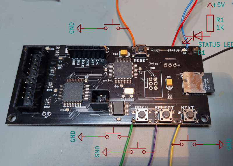
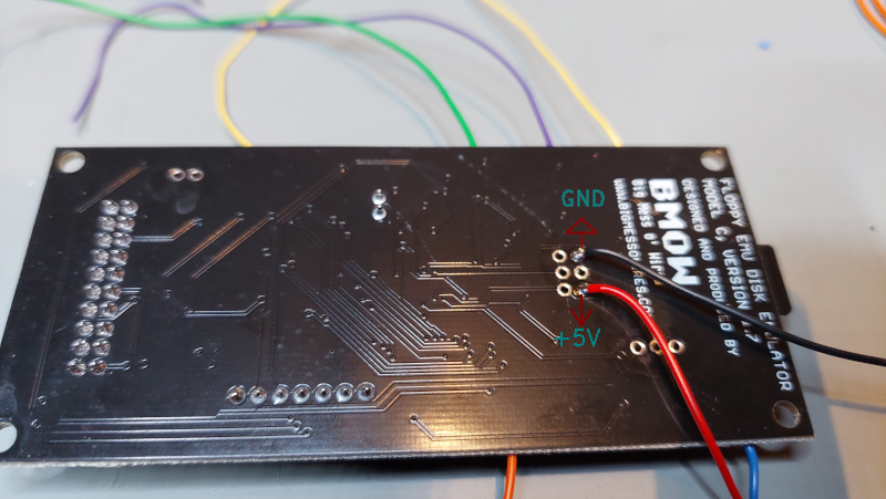
You can wire the ground lead (common for all push buttons) and the 5V (for the status LED) to the unpopulated debug connector in the middle of the FloppyEmu PCB. I soldered these two on the PCB’s bottom side, so they are almost “invisible” once the PCB is installed.
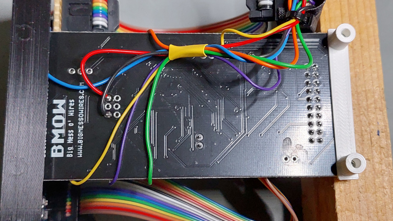
I suggest you solder all wires to a 2x5 pin header (or boxed header), so you can use a neat ribbon cable with plugs to connect the front button panel. The ribbon cable connects all four button signals, the status signal, ground and 5V – so three pins remain unused. If you wanted a power LED – just connect between ground and 5V (via a resistor, of course). See the schematics in the pcb folder for a suggested pin assignment of the pin header/ribbon cable.
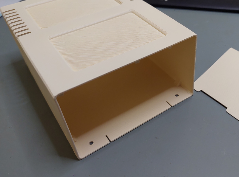
3D Print
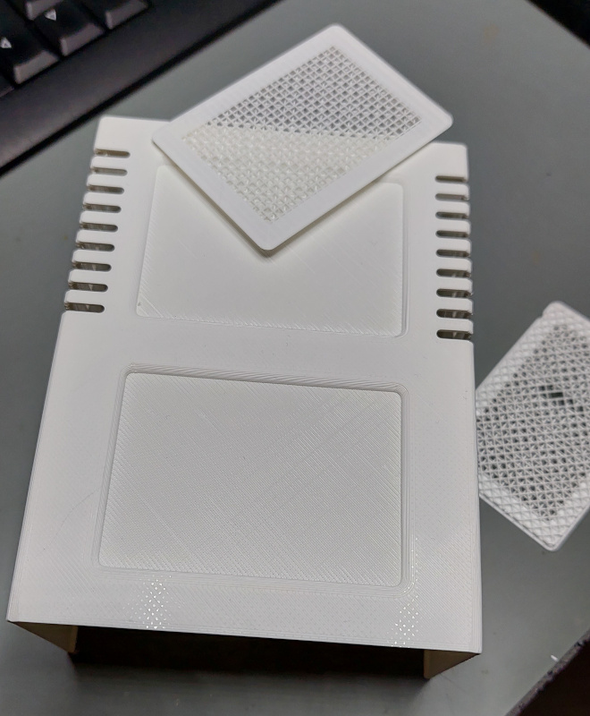
3D printing is straight forward. The models should be printed with their flat side facing downwards.
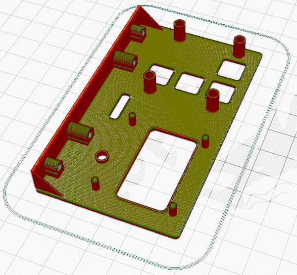
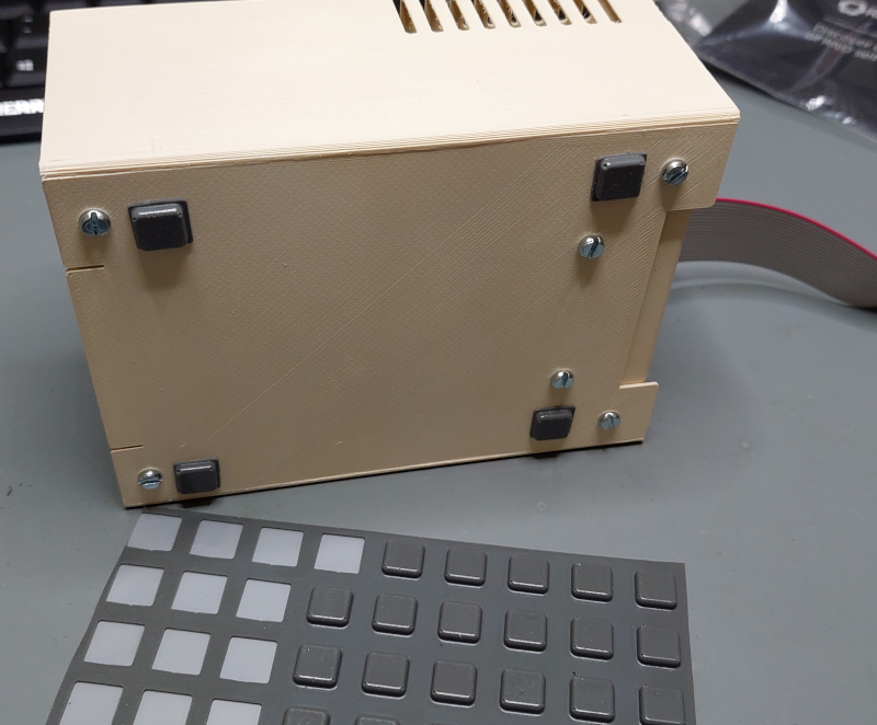
Preferably use white or light gray filament for the top shell, base plate, and for the rear panel. Use black filament for the front panel and the buttons.
The models are optimized to reduce 3D "supports", however, the top shell and the front panel still need "supports" to be enabled when printing.
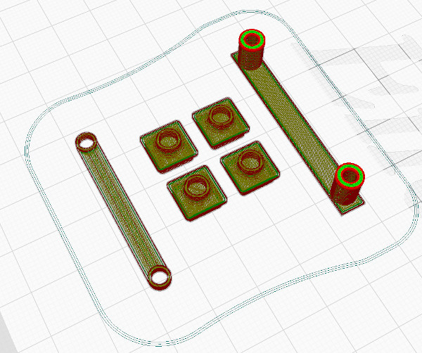
The buttons should be printed without supports. Two brackets are also printed: a bracket for the PCB (feet to tbe attached to the PCB rear). And a bracket for the cable strain-relief (cable can be attached to a mount at the top/rear of the shell).
The large grooves on the top shell do require supports though - since this model should be printed upside down:
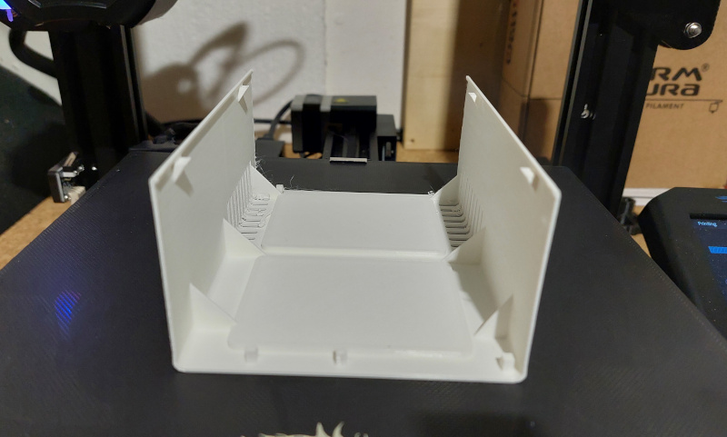
Carefully remove the printed "supports" to reveal the top grooves:
Print Duration
The top shell takes about 7 hours to print on an Ender 3v2. The front and rear panel require about 1:30 hours. The buttons and mounting brackets require about 30 minutes.
Assembly
Shell
The top shell and the base plate should be glued together. Make sure to completely cover the seam between these two elements, since these two parts were split for easier 3D printing, and the original Disk II does have different seams. Smoothing these seams (before applying beige "Apple II"-like paint - I used spray-paint) comepletely hides the seam. Glueing these two parts also provides extra strength: there should be no more wobble or flexing once the two parts are glued.
Front Panel
First, the PCB is directly attached to the front panel with two screws. The rear of the PCB is screwed to the printed mounting bracket ("PCB feet"). Then, attach the button PCB (perfboard of printed circuit board) with four screws to the front panel. Make sure the four buttons are working fine The push buttons only travel 0.25mm when depressed. If the PCB was slightly warped or the buttons are soldered unevenly, slightly adjust the distance between the PCB and the front-panel. Just unscrewing one of the four screws to release a bit of pressure may already be enough.
The LCD display is clipped into the front panel. The pegs should exactly fit to the original FloppyEmu LCD. If necessary, use glue to prevent the LCD from slipping from the little pegs (this should normally not be necessary though, if you do not clip and remove the LCD from the front panel too often).
Use a ribbon cable to connect the LCD to the original connector on the FloppyEmu PCB (make sure to connect the cable with the correct orientation!). Depending on the connector plugs, you may need to slightly bend the pins on the LCD, so they are angled 10-20° downward (may be necessary if the plug is too high and touches the top of the shell).
Eventually, when everything is connected, the whole assembly slides into the front of the 3D-printed shell.
The front panel and the rear-bracket of the PCB are fixed to the base plate with screws from the bottom of the shell.
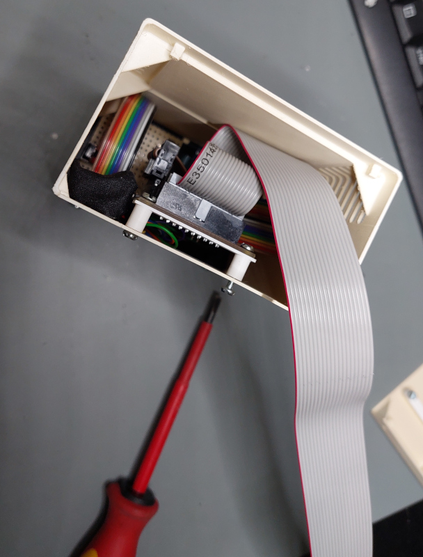
Once the PCB/front-panel is installed, connect the disk drive ribbon cable and use the printed cable bracket to attach the cable to the cable strain-relief at the top of the shell. This also guides the cable towards the cable slot in the rear-panel (photos above do not quite match: the cable strain-relief has since moved from the rear panel to the top of the shell).
Finally attach the rear panel with two screws from the bottom.
Almost done!
But remember: it's not complete... without rubber feet... :)
Done! :)
Stickers
By the way, check the sticker folder for a collection of stickers to decorate your device. Several variants of the rear sticker are provided. The designs are also available as GIMP image files (.xcf), so you can adapt the text to your needs.
The stickers are now also available in high quality here. Many thanks to khaibitgfx!
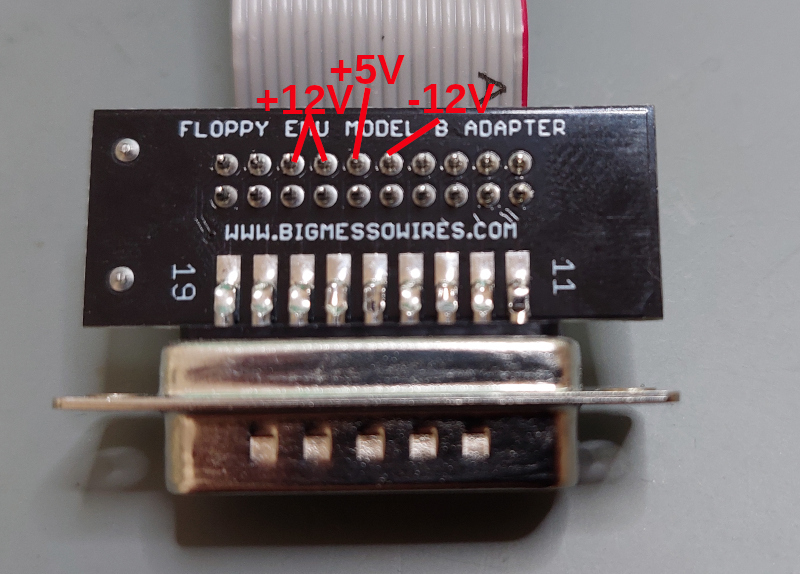
Bonus: Floppy Emu DB-19 adapter housing
The Floppy Emu DB-19 adapter is provided as a bare PCB only. It is usually connected to the back of your Apple II and rarely touched. However, you should still be careful with the adapter since the pins carry the +5V rail and also the +/- 12V rails. Since Disk II cable has the +/-12V rails connected to pins which are directly next to disk control and read/write signals (TTL/5V logic). A shortcut between these pins could easily damage the disk controller, the Apple II, or FloppyEmu (or all of them):
The 3D-printed plug adapter housing provides proper protection for the adapter. The adapter PCB slides right into the bottom part of the housing:
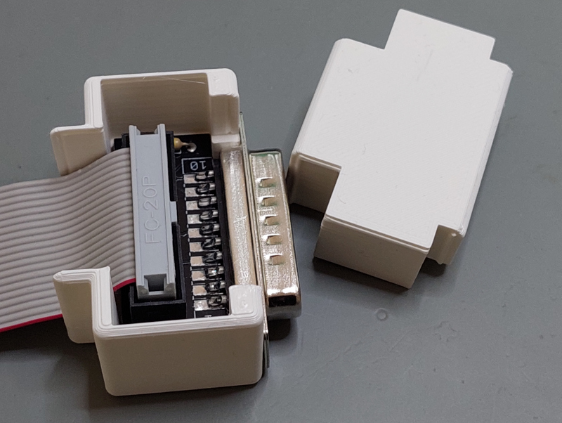
The top is printed with some notches, so it snaps right into place - and firmly holds the adapter PCB/plug:
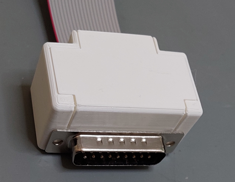
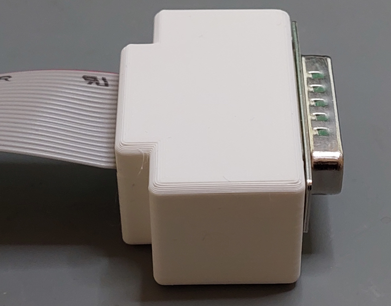
The result is a fairly bulky plug, but that's due to the clunky nature of the "PCB-box header-header plug-ribbon cable" assembly.