
ASCII Format
The ASCII format uses eight channels of the paper tape to represent a single character as shown in the diagram at left. Channel 8 is normally designated for parity check. The paper tape units of the PDP-8 family computers do not generate parity, and channel 8 is always punched.
377 (DEL, Rubout; all channels perforated) is used to “correct” typing errors and is ignored by paper tape rading programs.

RIM (Read In Mode) Format
RIM format tape uses adjacent columns to represent 12-bit binary information directly. Channels 1 through 6 are used to represent either addresses or information to be stored. A channel 7 punch indicates that the adjacent column and the following column are to be interpreted as an address specifiying the location in which the information of the following two columns is to be stored. The tape leader and trailer of RIM format tape must be punched in channel 8 only (octal 200).
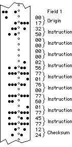
BIN (Binary) Format
BIN format tape is similar to RIM format except that only the first address of consecutive locations is specified. An address is designated by a channel 7 punch, and information following an address is stored in sequential locations after the designated address until another location is specified as an origin. The tape leader and trailer of BIN format tape must be punched in channel 8 (octal 200) only. Field setting is designated by channel 8 and 7 punch plus a three digit field number in channels 4 through 6.
The last two columns of a BIN format tape contain a checksum. The checksum is the sum (modulo 7777) of all preceding columns not containing a channel 8 punch (the field settings are not included in the checksum). When the BIN loader halts the PDP-8 with AC ≠ 0, then a checksum error occured while loading the tape.