FloppyEmuDiskIIEnclosure
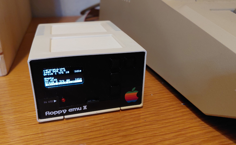
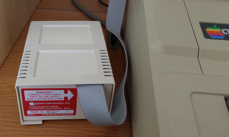
Project to create a 3D-printed custom enclosure for the "Big Mess of Wires" FloppyEmu (a SD card based disk drive emulator for the Apple II computer). The custom enclosure is shaped like Apple's historic "Disk II" drive, the first ever disk drive introduced by Apple in 1978.
Description
This project contains SCAD design files & STL files, stickers, KiCad PCB design, to create a 3D printed enclosure for a FloppyEmu. The enclosure is a look-alike of the historic and hugely successful "Disk II" drive, which Apple introduced in 1978 for the Apple II computer.
Credits
The idea for this 3D-printing project was triggered by similar ideas to create Disk II-shaped custom enclosures for the FloppyEmu in the AppleFritter forum - a forum for vintage Apple computer fans. See this discussion thread for more.
License
This project is released under the CreativeCommons License. See LICENSE.
The Apple logo is a registered trademark and copyright by Apple Computer Inc. Any images and photos which may show the Disk II-FloppyEmu enclosure with an Apple logo were only given as an example of how you could decorate your Disk II-FloppyEmu drive enclosure for your personal use. The 3D-printed Disk II FloppyEmu enclosure is not endorsed by Apple. This project does not grant you any rights or licenses to distribute any Disk II enclosures with an Apple logo.
Design
The 3D design is done with OpenSCAD. All files are available in the scad folder. SCAD provides You can also find a number of ready-to-use STL files in the stl folder.


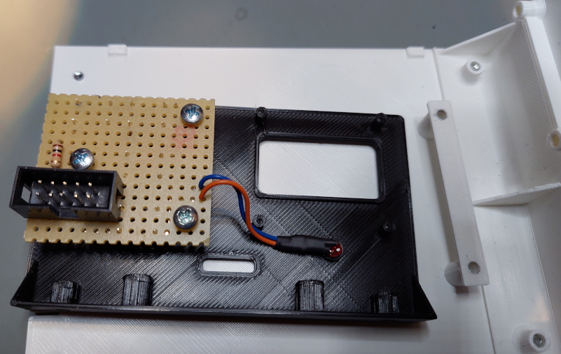
Button Panel
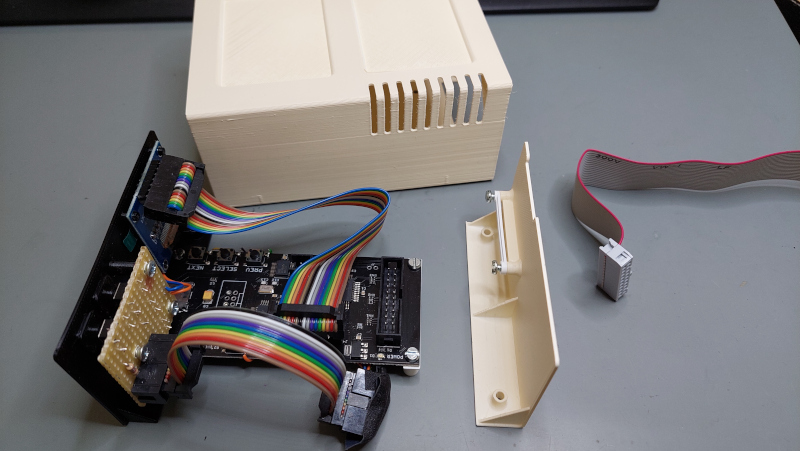
You will also need a button panel, so you can control FloppyEmu from the front panel. You can create the panel using a perfboard - or use the PCB design files to order a printed circuit board. You'll find schematics and also a KiCad PCB design project in the pcb folder.


Wiring the FloppyEmu
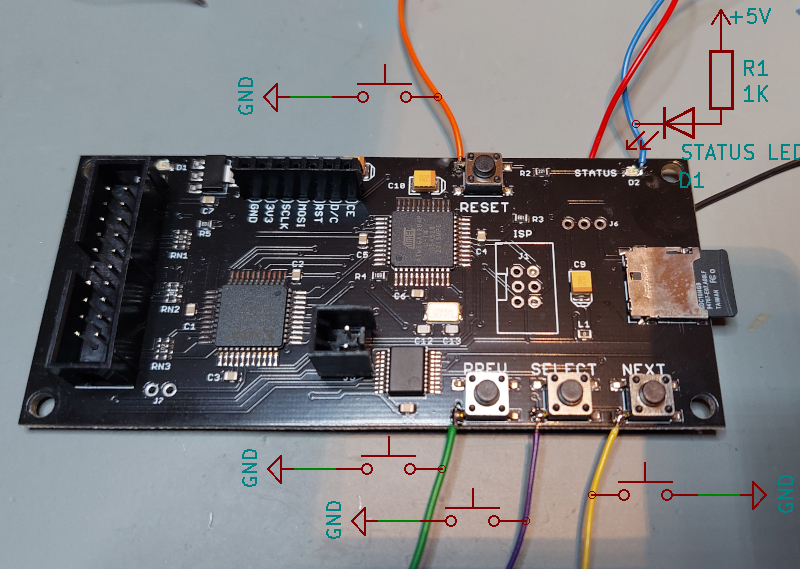
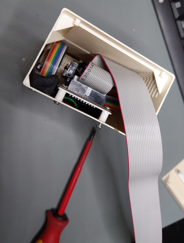
The FloppyEmu PCB does not provide convenient pins or solder pads to tap the button and LED status signals. However, it's still relatively easy to tap the required signals - as shown by these photos. The photos apply to the Revision C model of the BMOW FloppyEmu. For other revisions, better verify the wiring with a multimeter.
A single wire is enough for each push button is enough: all four push buttons, including the reset button, connect to common ground. The status LED, however, does not connect to ground: it's wired between the status output signal and +5V (via an appropriate resistor for the LED, of course). The only feasible place is to solder directly next to the LED. The status signal is on the right of the LED – as shown. Be careful when soldering – just touch the LED very briefly with the iron – otherwise the onboard LED will die.
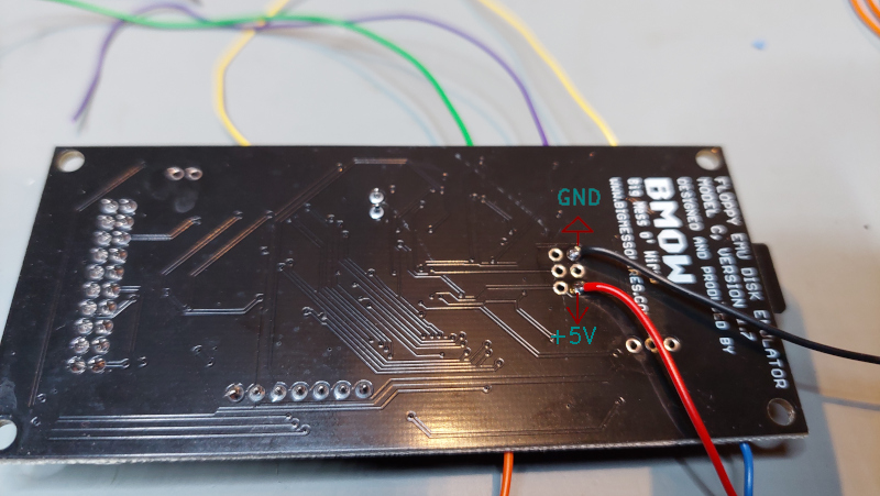
You can wire the ground lead (common for all push buttons) and the 5V (for the status LED) to the unpopulated debug connector in the middle of the FloppyEmu PCB. I soldered these two on the PCB’s bottom side, so they are almost “invisible” once the PCB is installed.
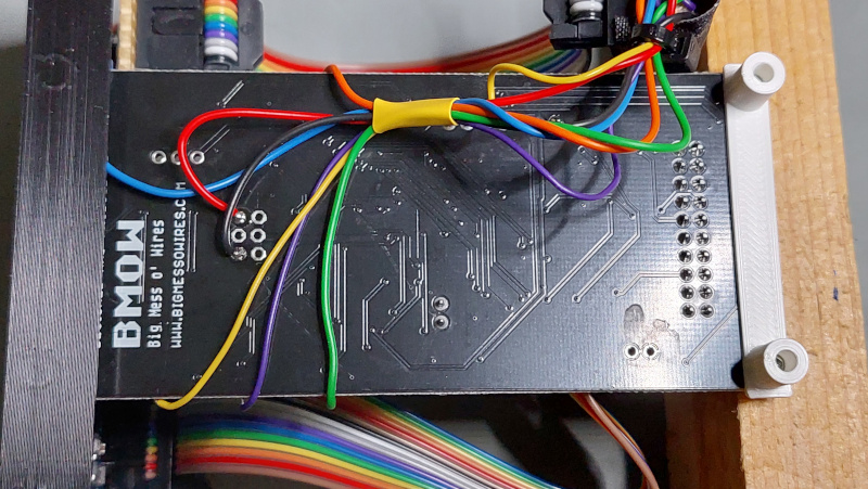
I suggest you solder all wires to a 2x5 pin header (or boxed header), so you can use a neat ribbon cable with plugs to connect the front button panel. The ribbon cable connects all four button signals, the status signal, ground and 5V – so three pins remain unused. If you wanted a power LED – just connect between ground and 5V (via a resistor, of course). See the schematics in the pcb folder for a suggested pin assignment of the pin header/ribbon cable.
3D Print
3D printing is straight forward. The top shell is printed upside down:
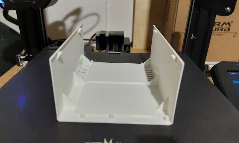
Afterwards, carefully remove the printed "supports" to reveal the top grooves:
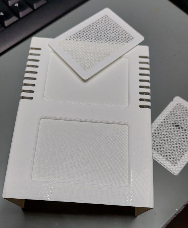
The top shell and the base plate should be glued together. Make sure to completely cover the seam between these two elements, since these two parts were split for easier 3D printing, and the original Disk II does have different seams. Smoothing these seams (before applying beige "Apple II"-like paint) comepletely hides the seam. Glueing these two parts also provides extra strength: there should be no more wobble or flexing once the two parts are glued.
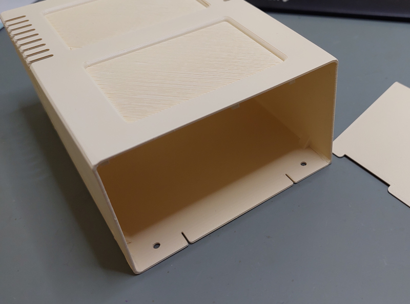
Assembly
Once the PCB is attached to the front panel, the whole assembly slides into the front of the 3D-printed shell. The PCB, the front and the rear panel are fixed with screws from the bottom of the shell.
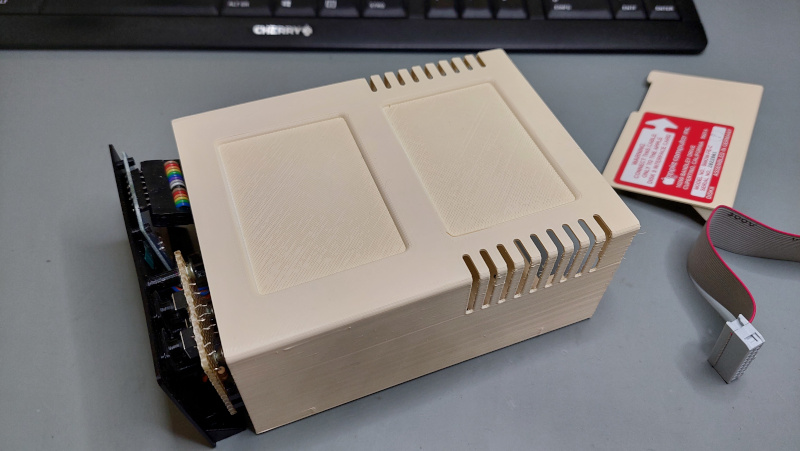
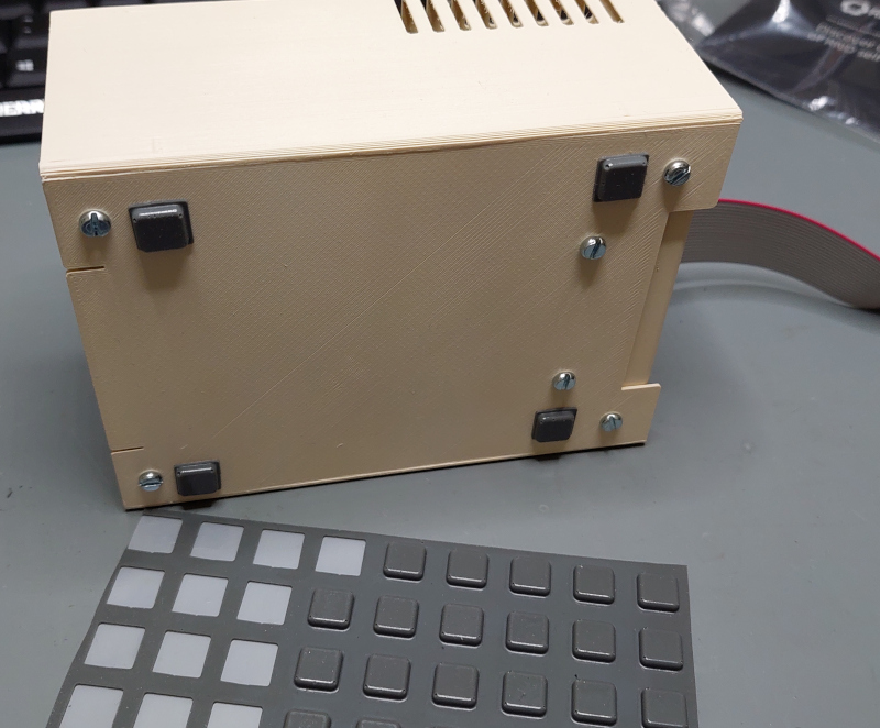
Remember: it's not complete - without rubber feet: