| .. | ||
| images | ||
| production-package | ||
| bom.ini | ||
| interface-ascii-bom.xlsx | ||
| interface-ascii.kicad_pcb | ||
| interface-ascii.pro | ||
| interface-ascii.sch | ||
| README.md | ||
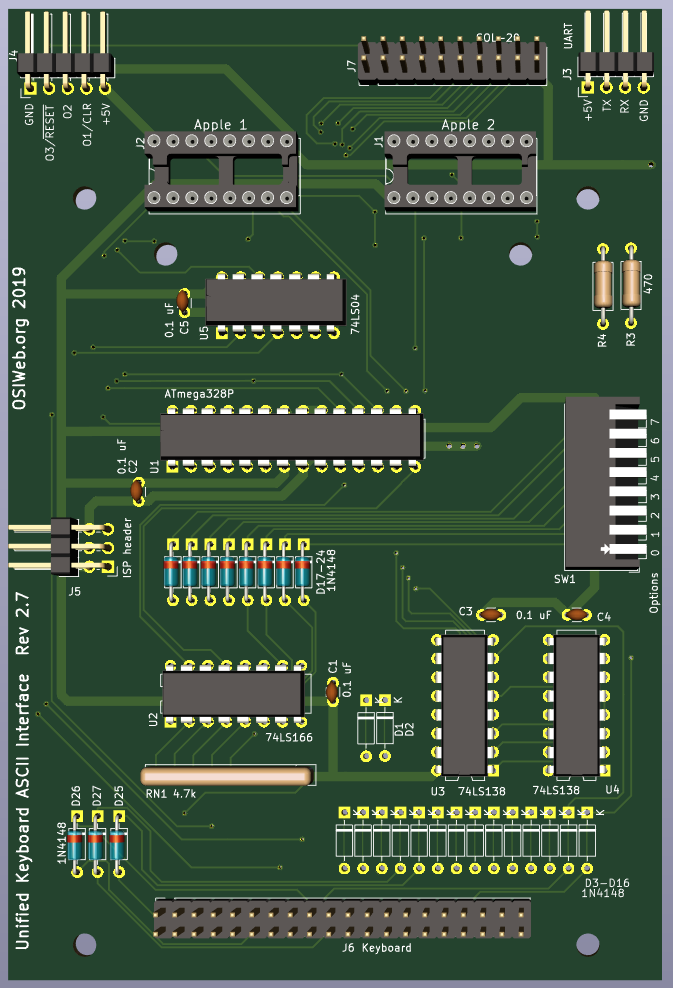
ASCII Interface - Atmega328p
This is is a key scanner module with parallel output, and optional serial output, supporting keyboards of up to 16 rows X 8 columns.
The ATMega 328P was selected for the sole reason that it is an architecture familiar to many hobbyists, with an accessible programming environment and ecosystem, in a DIP format that fits the retro look and is easy to solder for most hobbyists. All of the ICs, other than the microcontroller, are only present to compensate for the limited number of GPIO lines on this small 28-pin microcontroller. Using a bigger chip would greatly simplify the hardware and even slightly simplify the hardware layer of the firmware.
Features
- Parallel or serial output
- Up to 8 configuration settings via an up-to-8 position DIP switch
- Apple 1, Apple 2, and SOL-20 compatible outputs. Other configurations can be supported by making a custom cable.
- Can decode arbitrary keyboards up 16 rows by 8 columns.
- Supports up to 3 keyboard LEDs
- Supports up to 3 "special" host outputs, such as RESET, SCREEN_CLEAR, BREAK, etc.
Overview
-
The keyboard rows are driven by a pair of 74LS138 decoders, allowing 4 GPIO lines to drive 16 rows.
-
The columns are read in via an 8-bit shift register, controlled by 3 GPIO lines.
-
One 8-bit port is used for the parallel ASCII output.
-
Three GPIO lines are used to generate special outputs to the host. These could be RESET, BREAK, CLEAR, etc. Two of these may be configured as emulated open-collector drivers.
-
Three GPIO lines are used to control keyboard LEDs.
-
The DIP switch is wired into row 8 (of 0-15) to reduce RAM usage and speed up key scanning.
-
The top two parallel I/O bits can also be configured as UART I/O. This could be used to provide serial output instead or parallel output, to support a bootloader, or even to accept a serial input stream from another computer to send to the host as parallel ASCII data. This last application would require careful timing to avoid conflicts.
Assembly Notes
A typical build includes:
- the Microcontroller (U1)
- the 74LS166 shift register (U2)
- both 74LS138 decoder (U3)
- Diodes D17-D24 and D25-D27.
- The two resistors R3 and R4. If you are using the keyboard in only a parallel configuration or only a serial configuration, then you can jumper these resistors with a piece of wire.
- The resistor network RN1
- The DIP switch SW1
- The 40-pin keyboard connector (2x20 0.1" pin header)
- At least one output connector (Apple 1, Apple 2, or Sol-20)
- The 6-pin programming header J5.
The MINIMUM functioning circuit includes
- the Microcontroller (U1)
- the 74LS166 shift register (U2)
- One 74LS138 decoder (U3). Without the second decoder, the DIP switch is not supported, so only one keymap must be assigned as keymap 0 at compile time.
- The resistor network RN1
- The two resistors R3 and R4. If you are using the keyboard in only a parallel configuration or only a serial configuration, then you can jumper these resistors with a piece of wire.
- Any connectors required.
Optional components
Diodes D1-D16
NOT NORMALLY POPULATED.
These diodes are intended to prevent conflicts between high and low keyboard driver outputs. They allow the row drivers to pull rows low, but not high, emulating open collector outputs.
If you are attaching a keyboard with no diodes, then you only need to populate the diodes corresponding to rows on the keyboard. If the keyboard has 8 rows, then you may want to install 8 diodes corresponding to those rows.
Note that the footprints for these diodes include a copper jumper on the TOP copper layer. If you install any of these diodes, you should cut the jumpers for those diodes. Otherwise the diodes would do nothing.
If you are attaching a keyboard with a diode per key, then the diodes on the keys perform the same function, in addition to preventing "ghosting", so the per-row diodes do not need to be installed.
DIP switch and associated diodes
TYPICALLY INSTALLED.
If you don't want to select keymaps or options via the DIP switch, then you may omit the DIP switch and diodes. If you do this, then you will have to set the keymap and all preferences in the firmware. DIP switches, you can set all your preferences in the firmware, or just accept the default behavior, and skip the DIP switch and Diodes D17-D20 and D24-D27.
Second 74LS138 multiplexer (U4)
TYPICALLY INSTALLED.
You may omit this if
- your keyboard matrix has 8 rows or fewer
- AND you don't want any DIP options
- AND you only want one pre-compiled keymap.
The 74LS07 hex buffer (U5) and pullup R6
TYPICALLY INSTALLED.
The 74LS07 is needed if you are using LED2 or LED3 on the keyboard, or the OUT2 open collector output. If OUT2 is not open collector, then use a 74LS04 instead.
Diodes D21, D22, D23
TYPICALLY INSTALLED.
Some keyboards may not wire all keys into the matrix. For example, some other interface modules may assign special hardware functions to certain keys. Those keys are brought directly to the keyboard connector. For the classic keyboard, the POWER key, the '@' key, and the RUBOUT key are not directly wired. This module wires them into the matrix via D21, D22, and D23, respectively. For keyboards with no separately wired keys, these diodes may be omitted.