The encoder boards (ATmega328P, Atmega2560, Apple2(2560) can accomodate keyboard matrices with no diodes, by adding per-row diodes on the encoder board. For keyboards with per-key diodes (the typical use case), the per-row diodes are not needed, and therefore the footprints should be shunted by default, using a special shunted diode footprint. When diodes are installed, the shunt can be cut with an x-acto knife. Previous board revs had the correct footprint, but somehow the regular diode footprint was substituted on the last release of each of these PCBS. The correct footprint has been restored. |
||
|---|---|---|
| .. | ||
| images | ||
| interface-ascii-2560.kicad_pcb | ||
| interface-ascii-2560.pro | ||
| interface-ascii-2560.sch | ||
| README.md | ||
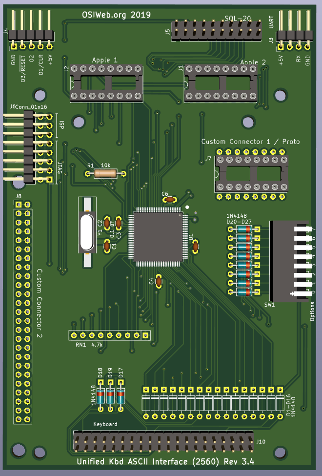
ASCII Interface - Atmega2560
This is is a key scanner module with parallel output, and optional serial output, supporting keyboards of up to 16 rows X 8 columns. This design uses the ATMega2560, since it's an easy port from the ATMega328P, which was initially selected for the sole reason of being familiar to hobbyists. The 2560 has much more I/O, which simplifies the design, assembly, and firmware, and opens up some additional possibilities.
Features
- Parallel or serial output
- Up to 8 configuration settings via an up-to-8 position DIP switch
- Apple 1, Apple 2, and SOL-20 compatible outputs. Other configurations can be supported by making a custom cable.
- Can decode arbitrary keyboards up 16 rows by 8 columns.
- Supports up to 3 keyboard LEDs
- Supports up to 3 "special" host outputs, such as RESET, SCREEN_CLEAR, BREAK, etc.
- Socket for custom connector
Differences from ATMega328P version
- Backward compatible with the ATMega328P version, with following enhancements:
- All the TTL outputs can be regualar push-pull TTL, open-collector, or open-emitter. In the 328P version, changing between regular TTL output and open-collector on Output 2 required changing an IC.
- The serial port no longer shares lines with the parallel output port, so both serial I/O and parallel output can be used at the same time without risk of conflict. However, serial I/O is not yet supported in the firmware.
- Because the rows are no longer driven by a 4-to-16 decoder circuit, and the columns are no longer read via a shift register, the row and column lines can be used for both input and output, which allows this board to interface with OSI keyboards directly (not yet supported in firmware).
Overview
- Two GPIO ports are used to drive the row outputs, and one GPIO port is used to read the columns.
- One 8-bit port is used for the parallel ASCII output.
- Three GPIO lines are used to generate special outputs to the host. These could be RESET, BREAK, CLEAR, etc. These may be configured as open-collector (Hi-Z for HI, GND for LO), or open-emitter (5V for high, Hi-Z for LO).
- Three GPIO lines are used to control keyboard LED, or other keyboard functions.
- A serial (UART) port is provided. This could be used to provide serial output instead or parallel output, to support a bootloader, or even to accept a serial input stream from another source to send to the host as parallel ASCII data.
- JTAG port is provided for programming and debugging
- Two custom connectors (16-pin DIP and 1x25 0.1" header) are provided to allow custom ASCII interfaces, or custom keyboard matrix interface.
Assembly Notes
- Solder the surface-mount microcontroller first. Be sure to match pin 1 to the dot on the silk-screen layer.
- Next, install the surface mount crystal, Y1. The orientation is not important.
- Next, solder in the Diodes D17-D19 and D20-D27
- Install all the capacitors. These are all 0.1 uF ceramic capacitors with 0.1" lead spacing. Many capacitors with 0.2" lead spacing are actually 0.1" emerging from the body, bent to 0.2", and can be straightened back to 0.1".
- Next, solder in the resitor R1 and Resistor network RN1.
- Install DIP switch SW1.
- Install connector J7
- Install the In-circuit Serial Programming (ISP) header, J6. (right-angle, 2x3 0.100")
- (Optional) If you will be the digital outputs, or if you will be attaching switches or other sources of open-collector signals (such as RESET), then install connector J4 (riginht-angle, 1x5 0.100")
- (Optional) If you will be using the serial port, install the serial header J3. (right angle, 1x4 0.100")
- If you will be using the Apple 1 connector, install the DIP socket J1 (16-pin dip). If you plan to insert and remove the cable many times, a dual-wipe socket may be preferable to machine-pin, since it has a lower insertion force, and you will be less likely to bend pins. If you plan to insert the cable once and leave it forever, I suggest a machine-pin DIP socket.
- If you will be using the Apple 2 connector, install the DIP socket J2 (16-pin dip). The note for the Apple 1 connector selection applies here as well.
- If you will be using the SOL-20 connector, install connector J5 (vertical 2x10 0.100")
- Do not populate diodes D1-D16. These diodes are jumpered short. If you are using a key matrix with no diodes, then cut the jumpers with an x-acto knife and populate the diodes.
- Do not populate RN1. The Microprocessor uses internal pullups, so this network is not required. The footprint is left in place in case a stronger pullup (in the 1K-10K range) is needed.
configuration or only a serial configuration, then you can jumper these resistors with a piece of wire.
- Any connectors required.
Optional components
Diodes D1-D16
These diodes are intended to prevent conflicts between high and low keyboard driver outputs. They allow the row drivers to pull rows low, but not high, emulating open collector outputs.
If you are attaching a keyboard with no diodes, then you only need to populate the diodes corresponding to rows on the keyboard. If the keyboard has 8 rows, then you may want to install 8 diodes corresponding to those rows.
Note that the footprints for these diodes include a copper jumper on the TOP copper layer. If you install any of these diodes, you should cut the jumpers for those diodes. Otherwise the diodes do nothing.
If you are attaching a keyboard with a diode per key, then the diodes on the keys perform the same function, in addition to preventing "ghosting", so the per-row diodes do not need to be installed.