Move future plans to separate file. Move BOM to separate file. Add more detail and pictures to v1.1. |
||
|---|---|---|
| .. | ||
| gerber | ||
| README.md | ||
| bluescsi_pb_v1.0.jpg | ||
| bluescsi_powerbook_v1.0.jpg | ||
README.md
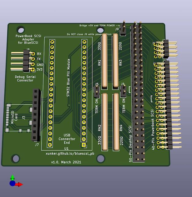
PowerBook adapter for BlueSCSI, v1.0
https://github.com/xunker/bluescsi_pb/v1.0
March 2021
Deprecation Notice
This design is deprecated and should no longer be used. Please see v1.1 instead.
Gerber files
Gerber files can be found here in the gerber directory.
Notes
First version. 50-pin-SCSI, termination and SD card worked first time, right out of the gate. However, problems:
- The screw holes are slightly too far in from edges
RETURNlines are not connected to signal ground- Can only power STM32 from
MOTORPWRor USB, no option to power it from fromTERMPWRalone - No option to disconnect STM32 from both
TERMPWRandMOTORPWRpower and use USB power alone without backfeeding
If you choose to use this board design, please do the following:
- break the
MOTORPWRtrace, as seen in this image - Solder a wire from any ground pin to one of the
RETURNpins (number 3, 4, 37 or 38) ofJ1. These are 1 column in from each edge, and and connected together. They are next to theMOTORPWRpins, the trace you broke above. - Ensure J9 ("bridge +5v and term power") is always shorted/jumped
Why the modifications? the MOTORPWR pins do not appear to be working the way I expect. The power was being disconnected at unexpected times and I could not see a pattern. Maybe it is a power-saving feature? Until I figure it out and update the board design, I recommend you power the device from TERMPWR as usual.