3.4 KiB
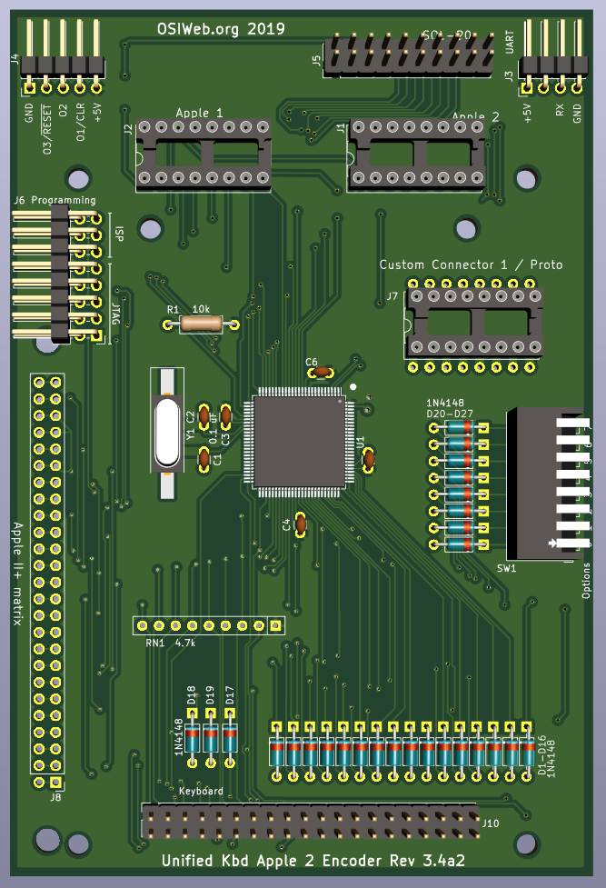
Apple II/II+ Encoder
This is a version of the ASCII interface wired up to be compatible with the Apple II/Apple II+ keyboard matrix. This board was broken out as a separate PCB from the Atmega2560-based interface board on which it was based, in order to keep the "custom" connector customizable on that board.
This board is otherwise identical to rev 3.4 of the ATMega2560-based ASCII interface board, and shares the same firmware and features.
Features
- Parallel or serial output
- Up to 8 configuration settings via an up-to-8 position DIP switch
- Apple 1, Apple 2, and SOL-20 compatible outputs. Other configurations can be supported by making a custom cable.
- Can decode arbitrary keyboards up 16 rows by 8 columns.
- Supports up to 3 keyboard LEDs
- Supports up to 3 "special" host outputs, such as RESET, SCREEN_CLEAR, BREAK, etc.
- Socket for custom connector
Assembly Notes
-
You may build this board as if it is a general purpose ASCII interface. In that case, you may want to avoid installing the 1x25 Apple2 keyboard header if it interferes with the target keyboard matrix. Also, for use with a key matrix that already has a diode for each key (or each row), you will need to install jumpers across the footprints for diodes D1-D16.
-
If you ARE building this board as an Apple 2 encoder, then you may omit:
- OMIT Sol-20 connector J5
- OMIT Custom connector J7
- OMIT D17,D18,D19 - These are used for the "classic" keyboard matrix.
- OMIT D7,D8,D15,D16 - These are diodes for rows 12-15, which are not used.
- OMIT the serial out connector J3 if you do not plan to use a serial output.
- OMIT the I/O connector J4, as all the I/O lines are routed through the keyboard connector.
- OMIT RN1. Not needed since the microprocessor uses internal pullups.
- If you will be using the keyboard with only an Apple 1 or Apple 2, then you do not need to install both the Apple 2 connector (J1) AND the Apple 1 connector (J2). You may install only the one you plan to use, and reduce the risk of plugging into the wrong socket (and possibly damaging the encoder).
-
Solder the surface-mount microcontroller first. Be sure to match pin 1 to the dot on the silk-screen layer.
-
Next, install the surface mount crystal, Y1. The orientation is not important.
-
Next, solder in the diodes D1-D7, D9-D14, and 20-D27
-
Install all the capacitors. These are all 0.1 uF ceramic capacitors with 0.1" lead spacing. Many capacitors with 0.2" lead spacing are actually 0.1" emerging from the body, bent to 0.2", and can be straightened back to 0.1".
-
Next, solder in the resitor R1 and Resistor network RN1.
-
Install DIP switch SW1.
-
Install the In-circuit Serial Programming (ISP) header, J6. (right-angle, 2x3 0.100")
-
If you will be using the Apple 1 connector, install the DIP socket J1 (16-pin dip). If you plan to insert and remove the cable many times, a dual-wipe socket may be preferable to machine-pin, since it has a lower insertion force, and you will be less likely to bend pins. If you plan to insert the cable once and leave it forever, I suggest a machine-pin DIP socket.
-
If you will be using the Apple 2 connector, install the DIP socket J2 (16-pin dip). The note for the Apple 1 connector selection applies here as well.