10 KiB
PowerBook adapter for BlueSCSI
https://github.com/xunker/bluescsi_pb
This project allows you to use BlueSCSI (STM32 SCSI emulator) in the Apple PowerBook, or in any other device that uses 40-pin 2.5in mobile SCSI devices.
Compatibility
Successfully used with my PowerBook 520c using the 40-pin connector. I have not yet been able to make it work with my PowerBook 145, however.
Using the 50-pin connector, I have successfully used it with an Apple IIgs, a Macintosh Classic II and a Macintosh LC.
Board Versions and Gerber Files
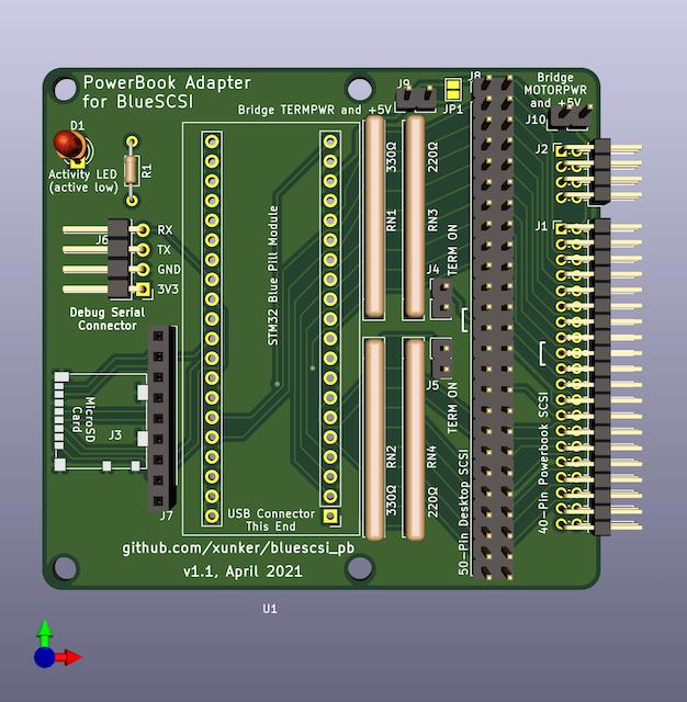
version 1.1 (April 2021) - current
Changes in order of importance:
- Mounting hole locations adjusted so they match an actual drive
- Connect
RETURNon 40-pin SCSI connector with signal ground - STM32 +5 is connected to
TERMPWRby default, via breakable jumper pad - Separate jumpers provided for powering via
TERMPWRorMOTORPWR- MOTORPWR is a separate +5v provided to run the drive motor and actuator
- This change will be helpful for debugging power issues where MOTORPWR appears to be inconsistent
- Activity LED (
LED_BUILTIN) broken-out if you want to have an external LED - Increased
TERMPWRtrace width - Traces and resistor packs are moved farther away from mounting holes to avoid potential shorts
- Back silkscreen marks location of the key pin (17) within the 40-pin connector
- Moved legends for J1, J2 and J8 so they are next to pin 1 on their respective connectors
- Corners rounded more
- Shorten board by about 5mm
- This is the shortest practical length to maintain all four screw holes
- Numerous changes to the routing of traces
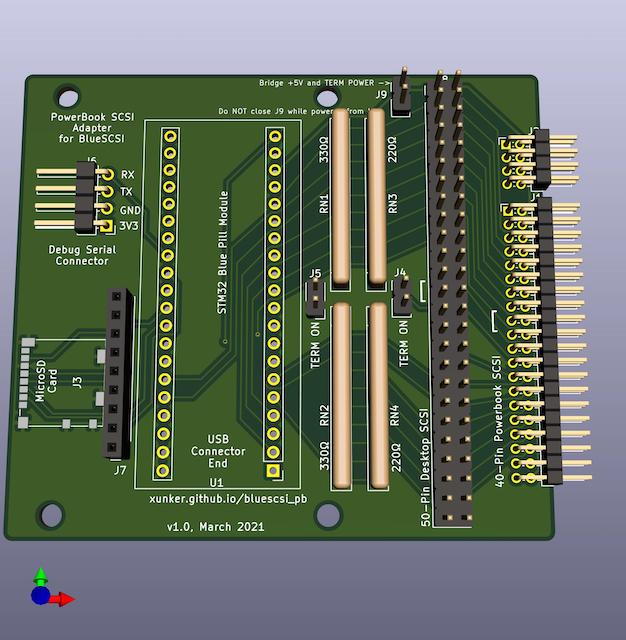
version 1.0 (March 2021) - not recommended, modify before using
First version. 50-pin-SCSI, termination and SD card worked first time, right out of the gate. However, problems:
- The screw holes are slightly too far in from edges
RETURNlines are not connected to signal ground- Can only power STM32 from
MOTORPWRor USB, no option to power it from fromTERMPWRalone - No option to disconnect STM32 from both
TERMPWRandMOTORPWRpower and use USB power alone without backfeeding
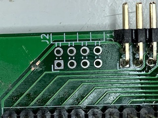
If you choose to use this board design, please do the following:
- break the
MOTORPWRtrace, as seen in this image - Solder a wire from any ground pin to one of the
RETURNpins (number 3, 4, 37 or 38) ofJ1. These are 1 column in from each edge, and and connected together. They are next to theMOTORPWRpins, the trace you broke above. - Ensure J9 ("bridge +5v and term power") is always shorted/jumped
Why the modifications? the MOTORPWR pins do not appear to be working the way I expect. The power was being disconnected at unexpected times and I could not see a pattern. Maybe it is a power-saving feature? Until I figure it out and update the board design, I recommend you power the device from TERMPWR as usual.
Future Plans
v1.1 is working well so I don't expect any majour changes for a while.
v1.2 (possible maintenance version)
Plans for a v1.2 (maintenance) may include:
- Jumper to toggle the activity LED
- So you can solder the LED and resistor, but disable it later if you prefer
- Break out power LED
- Provide a power LED (and a jumper toggle) breakout if an external power LED is desired
- Replace J4 & J5 with DIP switches or a single DPDT switch
v2.0 (possible full redesign)
If I continue to develop project in the future, I plan on a full redesign.
- Use termination ICs instead of resistors
- Lower power consumption
- More accurate termination voltage
- Switchable termination resistance (110-ohm or 2.5k-ohm) for short busses
- Attach J1 & J2 via the PCB edge to make it more like how an actual hard drive connects
- Less-expensive Micro SD card slot
- Automatic switching between TERMPWR, MOTORPWR or USB Power
If I want to fork the actual BlueSCSI firmware, I would like to add:
- Separate LEDs for read and write activity
- Read TERMPWR and MOTORPWR voltages and report them on the debugging connector
- LEDs to indicate with SCSI ID is being accessed
- Support OLED debugging display
Board Tour
40-pin connector (J1)
This is a 2.0mm, two-row, right angle header connector. It connects to the ribbon cable inside the PowerBook. Most ribbon cables have a "key pin" located at pin 17. If this is the case, you will need to break that pin off the connector on your board. The side the key is located on is indicated by the "[" symbol.
8-pin connector (J2)
This is also a 2.0mm, two-row, right angle header connector, located to the right of the 40-pin connector. This connector is *not required for operation, you do not have to solder headers to it if you don't want to.
This is used in some, but not all, PowerBooks. For example, it is present in my PowerBook 520c but it is not present in my PowerBook 145.
In some systems, it is used to change the SCSI ID of the drive, trigger spin-up and provide an activity LED. Since BlueSCSI selects SCSI IDs based on filename then this is not needed.
50-pin connector (J8)
This is provided to connect to a desktop SCSI connection. If you only intend to use this inside a PowerBook then this is not required.
If you do not use a shrouded connector, then you can still know the correct orientation of the SCSI cable by looking for the "[" symbol next to the connector, which represents the key cutout in a shrouded connector.
Termination Resistors Packs and Termination Enable Jumpers (J4, J5)
Solder two 220-ohm and two 330-ohm in to the correct positions. Please note the position of pin 1, it is different on either side.
Solder 2 standard 2.54mm header pins to J4 and J5, and then cap them with a jumper/shunt to enable termination.
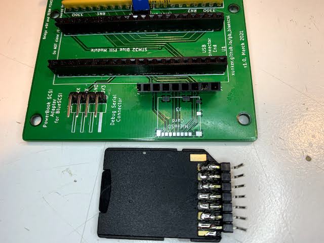
MicroSD card (J3) and SD Card Breakout (J7)
Pad J3 is used for a Molex 104031-0811 MicroSD card slot.
If you do not have the correct part (or don't like soldering SMD, which is totally understandable), you can also solder 2.54mm male headers to an SD-to-MicroSD adapter and connect it to J7.
Power selection jumpers (v1.1+ only)
By default the board is powered by SCSI termination power (TERMPWR), and is controlled by the joint JP1 (which is near J9).
Powering board by motor power (MOTORPWR)
If you want to have the board be powered by +5 motor power (MOTORPWR) instead of TERMPWR, you must
- Break joint JP1 with a small knife
- Solder a 2-pin header to J10 and short it with a removable jumper cap
This will power the Blue Pill module from MOTORPWR, but SCSI termination will still be powered by TERMPWR.
(Re)powering board by termination power (MOTORPWR)
If JP1 is broken and you want reconnect the board back to TERMPWR, you must either:
- Solder a 2-pin header to J9 and short it with a removable jumper cap
.. or ..
- Resolder JP1
Powering board by USB alone
If you want to power the Blue Pill module from USB power, you must:
- Break joint JP1 with a small knife
- Ensure that J9 AND J10 are NOT shorted
Activity LED (D1) (v1.1+ only)
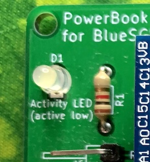
This is a breakout of the built-in LED that reflects disk activity. It is the same as the LED on the Blue Pill module itself. This part is optional and the module will work without it.
The signal is active-low, and current-limiting resistor for the LED is on the positive (anode) side of the LED. This way you can tap in to the cathode (negative) pin of the LED footprint to monitor drive activity from an external device directly if you need to do that.
Caveats
Termination
Although documentation for the IBM DHAS-2270 drive that originally came in my PowerBook 520c claims:
The drive does not have termination nor pull up resistors for SCSI interface
.. I have found that this adapter does not want to work as the internal drive unless you enable termination. The PB 520c does supply termination power to the internal drive (although it does not supply it to the external HDI-30 SCSI connector).
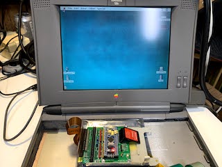
40-pin ribbon should not be seated fully on connector J1 (for me, at least)
On my PowerBook 520c, seating the drive cable fully on to connector J1 causes the BlueSCSI module to not work. I have found that leaving the ribbon cable slightly (like, 1mm maybe) off the connector makes the connection much more reliable. See picture below so see how much I am talking about:
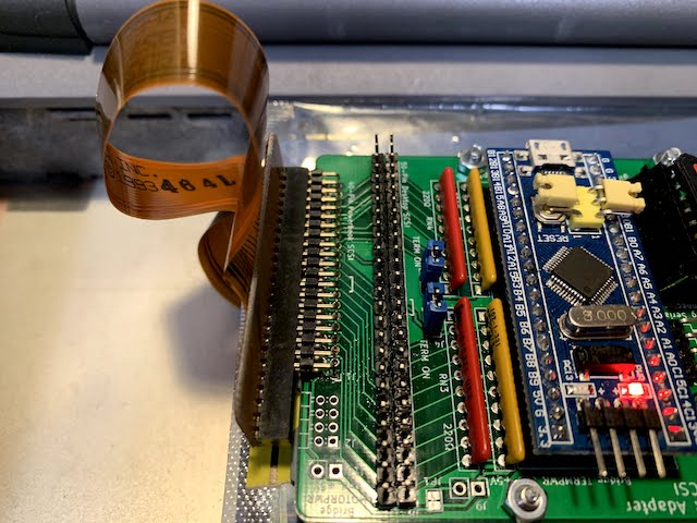
Click here for larger version of above.
Clearance
Most SCSI PowerBooks used 17mm-tall SCSI drives. In order for this board to fit in that height, you will either need to permanently solder the STM32 module directly to the bluescsi_pb board or to use "low-profile" female headers. If you use standard-height headers, you will need a space of 19-20mm.
Even with low-profile headers, you may have to bend the "boot select" jumpers on the top of the STM32 module off to the side.
Using the 50-pin connector at the same time as the 40-pin connector
I recommend that you do not use the 50-pin and 40-pin connectors at the same time. If you know what you are doing then you are welcome to try, but please be careful.
Credits
This project would not be possible without the work done by ztto, Tambo, Eric Helgeson, and many others.
The "Blue Pill" footprint was originally created by Yet-Another-Average-Joe.
License
See LICENSE.md.