mirror of
https://codeberg.org/cryu/micro-sci-a2-controller
synced 2026-01-22 15:16:12 +00:00
74ls245
Weyoun
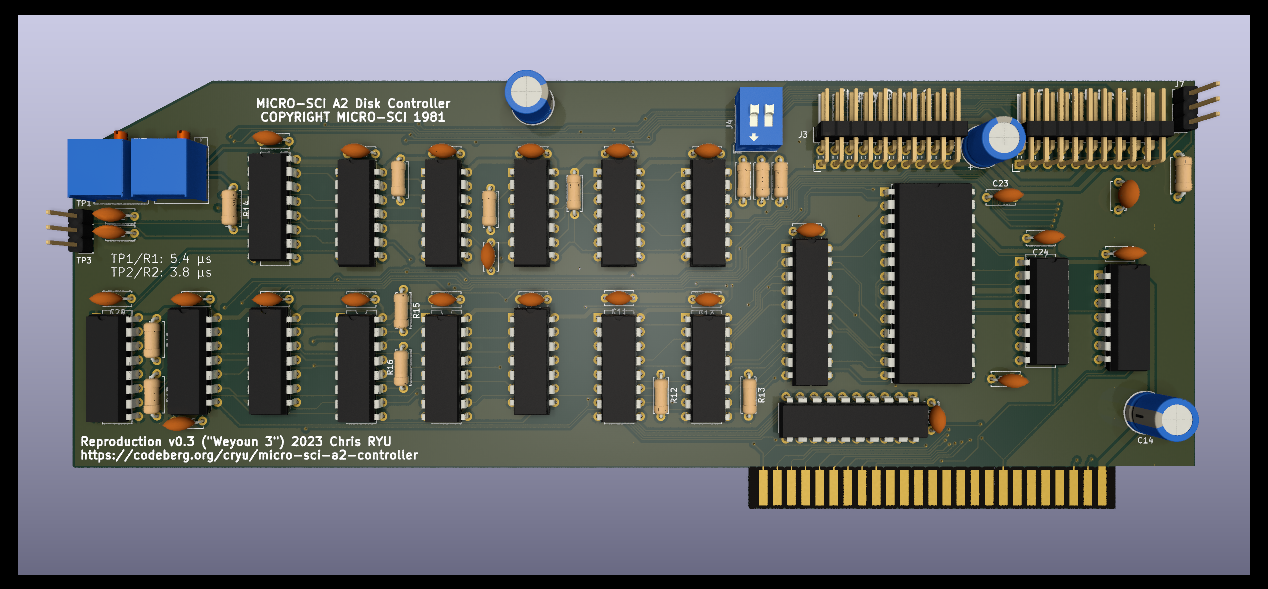
Weyoun is a clone of the Micro-SCI / Franklin floppy drive controller.
Features
Revision history
Weyoun 1 was a direct clone, reverse-engineered from a Micro-SCI board. It was cross-checked with a Franklin-branded board, as well as the (belatedly discovered) official Franklin schematic (included in doc/service_and_schematics.pdf)
Weyoun 2 had the following enhancements over the original design:
- the 2708 EPROM has been replaced with a more-common 2716/2732 EPROM
- decoupling capacitors have been added
- footprints for all capacitors and resistors have been modernized
- firmware EPROM bank selection jumpers replaced with a DIP switch
- obsolete MPS-U51 transistor replaced with modern equivalent
- clearly-marked calibration test points have been added
- ground pours used to increase operational stability
- support for using Floppy Emu in dual-drive emulation mode with one cable
Weyoun 3 has the following enhancements over Weyoun 2:
- a 74LS245 octal buffer has been added to the data bus, to facilitate the use of a no-slot clock under the firmware EPROM
- the EPROM has been changed from 2716/2732 to 2764/27128/27256 to allow a no-slot clock to be placed in the socket without modification
- all logic chips, except the 74LS245 at U19, can and should be 74HCT/74ACT to reduce power consumption to a fraction of the original design
- the transistor that switched the +5VDC power line for half of the board has been eliminated -- with CMOS, the board can stay powered at all times
- the circuit board layout has been streamlined in alignment with the above bullet points
Firmware images can be built via the Makefile in the firmware subdirectory. The build framework requires cc65.
EPROM bank select switches (J4)
- 1:off 2:off - firmware "put jumpers here" splash screen (0x0300)
- 1:off 2: on - 13-sector firmware (0x0200)
- 1: on 2:off - 16-sector firmware (0x0100)
- 1: on 2: on - controller test firmware (0x0000)
Calibration procedure
- set J4 to on/on ("controller test firmware")
- connect oscilloscope to TP1
- start machine
- execute "call 50688"
- execute "AAW" (and immediately hit ESC)
- adjust R1 until waveform period is 5.4 microseconds
- connect oscilloscope to TP2
- execute "99W" (and immediately hit ESX)
- adjust R2 until waveform period is 3.8 microseconds
- card is now calibrated, power off machine and set J4 to "16-sector firmware"
Construction notes
- The second floppy drive header (J3) can be omitted if this controller is used exclusively with a FloppyEmu. Populate R11 and connect pins 1 and 2 on J7.
- All discrete logic ICs (except U19, the 74LS245) should be CMOS (74ACT, 74HCT). As is unfortunately usual with the Apple ][, U15 must be LS due to timing issues.
Description
Languages
Assembly
91%
C
5.6%
Makefile
3.4%
