Overview
You can optionally attach the PiSCSI Control Board to your PiSCSI pHAT. It's designed to be used for a minimal hardware-based UI for PiSCSI which sits on top of the full-size pHat or PiSCSI Zero board and it's made to match the PiSCSI Zero size and holes. The PiSCSI Control Board communicates with the Pi through the I2C bus. It features an OLED display, two buttons and a rotary encoder. The PiSCSI Control Board is used along with the PiSCSI Control Board software (ctrlboard) which is/will be bundled with PiSCSI.
The PiSCSI Control Board software currently covers the following functionality:
- Attaching/Inserting/Detaching/Ejecting disk images to the SCSI slots.
- Displaying information about the attached/inserted disk images.
- Loading Profiles
- Shutting down the Pi
Usage
The UI navigation is simple and is entirely based on the rotary encoder. The software essentially consists of three navigation layers:
- The SCSI slot screen
- The slot action menu
- Follow-up menus to the slot action menus.
In each screen, the first menu entry is always "return" which allows you to go back to the previous menu navigation layer.
In addition, there are two buttons on the Control Board. The actions on these buttons are currently fixed and preconfigured. Both buttons open a cycle menu that allows to cycle between multiple entries by pressing the buttons multiple times. The first cycle entry is always "Return ->" which prevents accidental button actions. If a cycling selection isn't changed for 3 seconds, the selected entry is chosen.
- Button 1 (top button): Load Profile
- Button 2 (bottom button): Shutdown
SCSI Slot Screen
When the software loads, a screen with the 7 SCSI slots is shown with possible. By pressing the rotary encoder on a SCSI slot, the slot is selected for the slot action menu.
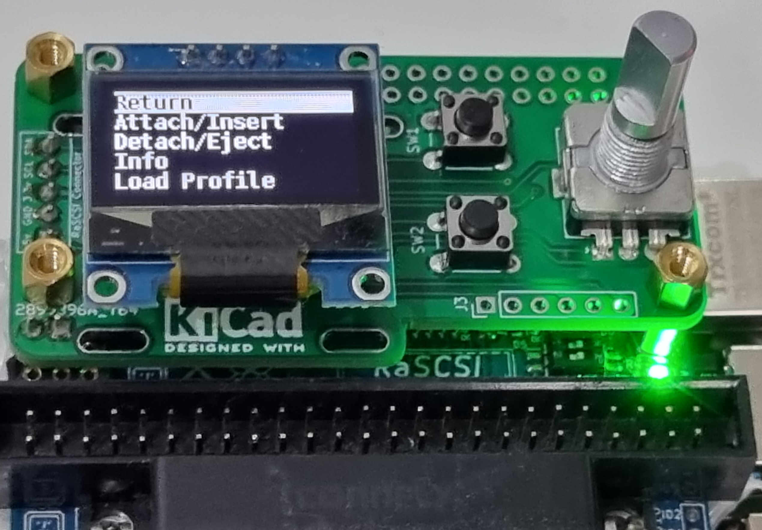
Slot Action Menu
In the slot action menu, the following actions can be performed:
- Attach/Insert: inserts/Attaches an image. When selected, a follow-up menu opens where the image to attach/insert can be chosen.
- Detach/Eject: detached/ejects an image from a slot. When selected, the current image on the chosen slot is detached/ejected. If an image is ejected, it is detached when performed a second time on an empty drive.
- Info: displays information such as ID, LUN, filename, image type etc. of the image on the selected slot. On empty slots, only "Return" is shown.
- Load profile: opens a follow-up menu with the profiles stored in the PiSCSI web interface. When a profile is selected, it is loaded.
- Shutdown: When selected, the Raspberry Pi performs a graceful shutdown.
Screensaver and auto-refresh
The screen of the menu automatically goes blank after 25 seconds. The menu can be woken up again by pushing a button or moving the rotary encoder.
The SCSI ID list is refreshed every 6 seconds when active.
Hardware Assembly
There are two assembly variants of the control board:
- Variant 1: the PiSCSI hat, either the full-size one or the Zero hat, must have stacking headers installed for this variant. If the PiSCSI hat has those GPIO stacking headers soldered, it's possible install a female GPIO pin header on P1 to connect the control board to the PiSCSI hat.
- Variant 2: if the PiSCSI hat does not have stacking headers installed, female 2.54mm pin header sockets must be installed on the PiSCSI full-size hat J3 and J4. The PiSCSI Zero hat cannot be used with Variant 2 as the necessary pin on J4 does not exist.
The control board contains 0805 SMD components as well as a 16TSSOP IC. Hence, not everyone might feel comfortable soldering these surface-mount components. Assembly files for JLCPCB can be found in the GIT repository under hw/ctrl_board_v1p5/gerbers: ctrl_board_bottom-pos.csv (CPL File) as well as ctrl_board_jlcpcb_bom.csv (BOM File). Make sure to select assembly of the bottom side for the assembly service.
The URLs provided are just examples.
| Quantity | Label | Description | Link |
|---|---|---|---|
| 13 | R1-R13 | 10k 0805 resistors | |
| 1 | C1 | 100nF 0805 ceramic capacitor | |
| 2 | SW1,SW2 | 4 pin push button 6x6mm | |
| 1 | SW4 | Rotary encoder 15x12mm with push button | |
| 1 | J2 | 0.96" I2C SSD1306 128x64 pixel OLED | |
| 1 | U1 | PCA9554APW,118 I2C I/O Expander 16TSSOP | |
| 1 | P1 | Variant 1: GPIO pin header female | |
| 1 | J4 | Variant 2: 2 pin 2.54mm pin header aux GPIO connector | |
| 1 | J1 | Variant 2: 4 pin 2.54mm pin header PiSCSI connector |
Additional notes for the assembly.
- For variant 2, JP4 needs to be solder-bridged.
- For the PiSCSI control board hat to sit tight and stable, it's useful (or let's rather say essential) to install four M2.5 spacers between the PiSCSI hat and the control board hat.
- Newer PiSCSI boards have 6 pins on the J4 "Oled" connector. These will mate up with the 6 pin connector of the control board. Older PiSCSI boards only have 5 pins on J4. These will also need to use "GPIO9" from connector J5.
Hardware Installation
No matter what the chosen variant is, the control board hat usually sits on top of the PiSCSI hat. There might be custom case or enclosure designs that require a cable between the PiSCSI hat and the control board, for example, when the control board is installed in a 19" casing or similar.
Software Installation
The installation of the Control Board UI is integrated into easyinstall.sh as as separate installation option under experimental features. It is declared experimental as it hasn't been widely tested by end users yet. However, the UI has been tested on multiple raspberry pi devices and should work fine for most. At some point in the future, it will probably be merged with the piscsi OLED service.
Please note that the installation of the Control Board UI automatically disables the rascsi-oled service and vice-versa as only one of them can be active at the same time.
The easyinstall.sh script also takes care of detecting your Raspberry Pi model and automatically enabling i2c and adjusting i2c baudrates that worked well during tests.
Additional Details
- The Control Board UI cannot be used with an OLED alone. The complete PiSCSI Control Board hardware with OLED, rotary encoder and two buttons is required. The Control Board UI detects on startup whether all necessary devices are present.
- The Control Board UI currently requires and SSD1306 128x64 display. While the Control Board UI generally supports different displays (such as SH1106) and resolutions, this is currently not enabled and accessible for users.
- On Pi 3, Pi Zero 2 and Pi 4 models, transition animations are enabled. For smaller/older models, animations are disabled. Thus, the experience might be less good with smaller/older models.